Wall Panels
The wall panel element allows you to easily model walls for in plane loads. Wall panel data may be viewed and edited in two ways: graphically in the Wall Panel Editor or in the Wall Panels Spreadsheet.
Drawing Wall Panels
There are several graphic-editing features that make the creation and modification of models quite easy. Use the Insert and Modify menus or the Drawing Toolbar to use these features in the model view. To create new wall panels, you can draw them using a drawing grid or draw "dot to dot" existing joints. Once you have created these items you may use other graphic features to apply loads and set boundary conditions.
You can set many of the wall panel properties up front or you can modify these properties after you draw them. Modifying properties is discussed in the next sections. See the Wall Panels topic for information on wall panels and their properties.
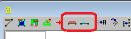
The Draw Wall Panels  button lets you graphically draw wall panels in your model. Enter the appropriate wall panel parameters, click OK and draw wall panels between existing joints or on the drawing grid. You will also notice that the coordinates of the joint or grid point that is closest to your cursor are displayed in the lower right hand corner of the model view. The new wall panels will be shown on screen and will be recorded in the Wall Panels Spreadsheet.
To actually draw a wall panel, you have two options. One way is to modify your Drawing Grid according to how you wish to lay out your wall panels and use the Create Wall Panels by Clicking on Grid Areas option. Wall panels can then be created by clicking in the grid areas formed by the intersecting grid lines. As you click on an area, a wall panel will automatically be created in that area. The second option is to create wall panels by drawing them one joint at a time. First click on the grid point or joint that you want to be the "A" joint for the plate, then the "B" joint, "C" joint, and "D" joint in either clockwise or counter-clockwise order. The wall panel will "stretch" like a rubber band as you draw from joint to joint.
Note:
- You must draw wall panels rectangular.
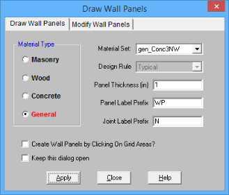
The parameters shown are the same parameters that you would enter on the Wall Panels Spreadsheet.
-
If there is not a model view already open then click  on the RISA Toolbar to open a new view and click
  to turn on the Drawing Toolbar if it is not already displayed.
- If you are not drawing between existing joints, you will need to create a drawing grid or define joints on the Joint Coordinates spreadsheet.
- Click the Draw / Modify Wall Panels
 button and select the Draw Wall Panels tab. Then set the wall panel properties.
- Click Apply to start drawing wall panels by clicking on the joints or grid points with the left mouse button.
- You must click four points in a clockwise or counter-clockwise order.
- Or, click in grid areas.
-
To stop drawing altogether right click or press the Esc key.
- To draw more wall panels with different properties, press CTRL-D to recall the Wall Panel Properties settings.
- You may also specify or edit wall panels in the Wall Panels Spreadsheet.
- You may also view and edit wall panel properties by double-clicking on a wall panel.
- You may undo any mistakes by clicking the Undo
 button.
- Drawing clockwise or counter-clockwise determines the panel's local axes directions. See Wall Panel Local Axis for more information.
Modifying Wall Panels
There are a number of ways to modify wall panels. You may view and edit the member data in the Wall Panel Spreadsheet, you may double-click a wall panel to view and edit its properties, or you can use the Modify Wall Panels tool to graphically modify panels.
The graphical Wall Panel Modify tool modifies the properties of wall panels that already exist in the model. To use this tool, specify the properties you want to change and then select the wall panels that you want to apply these changes to. Wall panels can be modified one-at-a-time by selecting the Apply Entries by Clicking option. This will change the mouse cursor to a modify tool which applies to any wall panels which you click on. A group of selected wall panels can be modified all at once by using the Apply Entries to All Selected option. See the Graphic Selection topic for more on selecting.
The Out of Plane Flip option will flip the openings and regions within the wall. If you draw in your openings opposite of what you meant then this tool can be useful.
The parameters shown are the same as those used to define new wall panels.
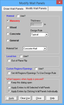
The Use? check boxes next to the data fields indicate whether the particular parameter will be used or not when the modification is applied. If the box next to a field is checked, that parameter will be applied to any selected wall panels. If the box is NOT checked, the parameter will NOT be applied, even if a value is entered in the field. This allows you to easily change one or two properties on wall panels without affecting all the rest of the properties. Note that if a no value is entered in a field (i.e. the field is blank) and the corresponding check box is checked, clicking “Apply” will have the effect of clearing the data for that field.
- If there is not a model view already open then click on the RISA Toolbar to open a new view and click to turn on the Drawing Toolbar if it is not already displayed.
- Click the Draw / Modify Wall Panels
 button and select the Modify Wall Panels tab. Then set the parameters for the new wall panels. Check the Use? Box for the items to apply.
- You may choose to modify a single wall panel at a time or to an entire selection of wall panels.
- To modify a few wall panels choose Apply Entry by Clicking Items Individually and click Apply. Click on the wall panels with the left mouse button.
- To modify a selection of wall panels, choose Apply Entries to All Selected Items and click Apply.
- To modify more wall panels with different parameters, press CTRL-D to recall the Modify Wall Panels settings.
- You may also modify wall panels in the Wall Panels Spreadsheet.
- You may undo any mistakes by clicking the Undo
 button.
- The thickness option is only available if you are choosing a General or Concrete material. Wood and Masonry require you to change their thickness in the Design Rules spreadsheet.
- For existing models of version or earlier, all wall panels will be brought in using Custom regions/openings. Here we provide an option that will reset all wall panels to base their design on the Wall Design Rule.
Wall Panel Spreadsheets
Another way of editing wall panels is through the Wall Panel Spreadsheet. This spreadsheet is accessible through the Data Entry Toolbar and includes data on two tabs: Primary and Advanced.
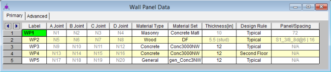
The following data columns hold the primary data for the wall panels:
Wall Panel Labels
You may assign a unique label to any or all of the wall panels. You can then refer to the wall panel by its label. Each label has to be unique, so if you try to enter the same label more than once you will get an error message. You may relabel wall panels at any time with the Relabel Wall Panels option on the Tools menu.
Wall Panel Joints
The A, B, C, and D joint entries are used to define the 4 corner joints of a wall panel. The joints must all lie on the same plane, be oriented parallel to the vertical axis and be entered in either a clockwise or counter-clockwise sequence. They can not be adjusted from the spreadsheet.
Wall Panel Material Type and Material Set
The material set label links the wall panel with the desired material defined on the Material Spreadsheet.
Note
- Currently wall panels can only be made up of concrete, masonry, wood, or general materials.
Wall Panel Thickness
The thickness field on the Wall Panels Spreadsheet is the thickness of the element. This thickness is constant over the entire element. Note that the thickness for Masonry and Wood wall panels are set in the Design Rules spreadsheet. For concrete and general material walls the value is defined here.
Design Rule
This allows you to choose a specific design rule from the Design Rules spreadsheet. The design rule is where you can specify very detailed information for the wall.
Panel/Spacing
This shows the current panel for masonry and wood walls. Wood and masonry walls can require an iterative solution. This means that the panel properties used for a wall panel may change from solution to solution, so here is the place where that information is displayed. Note that the panel properties also show up in the output.
When you select a design rule for a wall panel, there may be a range of sheathing call-outs, stud spacings and bar/grout spacings. At the initial solution the program simply uses the first item in the list that meets the criteria of the design rule and then the optimization starts from there. This initial criteria is what will show up in the Panel/Spacing column. After you optimize your wall this panel criteria may update/change. If you want to reset all of these values to the original values, simply press the  button when in the Wall Panels spreadsheet.
Note:
- For masonry walls we show the current bar/grout spacing.
- For wood walls we show the current sheathing call-out and the current stud spacing.
- For concrete walls this column is not applicable, as the stiffness of the wall is not affected by the program optimiziation.
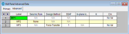
Design Method
This is a column specific to wood wall panels and allows you to choose which design method you choose to work with: Segmented, Perforated or Force Transfer. See the Wood Wall Panels topic for more information. These design methods are not applicable for concrete, masonry, or general wall panels.
Note:
- Currently, wood wall panel design is only available for NDS design.
SSAF (Shear Stiffness Adjustment Factor)
This is a factor specific to wood wall panels that allows the user to manually adjust the shear stiffness of a particular wall panel. Because the program uses a finite element solution the program does not automatically consider some contributions to the FEM deflections, such as nail slip. With this adjustment factor the user can match up the deflections from their hand calculations with the FEM joint deflections at the top nodes in the wall.
Icr
These values are considered for both masonry and concrete wall design and allow you to modify the stiffness of the wall for cracking considerations. This value will be multiplied by the Igross of the wall.
Masonry Walls
By default (if left blank) the program will use a value of 0.50. This value comes from Section 3.1.5.2 of the ACI 530-11 code. If you have performed a cracked section analysis or want to override this default you can input it directly here.
Concrete Walls
By default (if left blank) the program will use a value of 0.70. This is the minimum factor for beams per ACI 318-14 Section 6.6.3.1.1 (ACI 318-11 Section 10.10.4.1). If you have performed a cracked section analysis or want to override this default you can input it directly here.
For service
level analysis, the level of cracking will be significantly less. Therefore, the stiffness used in your analysis should be representative
of the reduced loading and reduced cracking. Per the ACI 318-14 Section R6.6.3.2.2 (ACI 318-11 Section R10.10.4.1), the program will account for this increased stiffness by applying
a factor of 1.43 to the cracked section properties for any load combination
that has the “Service Load” flag checked on the Design tab of the Load
Combinations Spreadsheet
Note:
- This factor will only be used if the Use Cracked Sections checkbox is checked in the Concrete tab of Model Settings.
- This factor (or 1.43*Icr) can not be greater than 1.0.
K Factor
This is the effective length factor and is available concrete, masonry and wood walls. If left blank this will be taken as 1.0.
- For masonry this factor affects ACI 530-11 equations 2-16, 2-17, 2-19, 2-21, 2-22, 3-11, 3-12, 3-18, 3-19, and Section 3.3.5.3.
- For wood this affects the Cp factor calculation (specifically FcE) for wood compression capacity for both studs and chord design.
Cm
This input controls the Cm calculation for P-Little Delta calculations for concrete wall panels. If this is left blank the program will auto-calculate this value. See the P-LIttle Delta section of the Concrete Wall - Design topic for more information.
Inactive
This column allows you define a wall panel as inactive or excluded. Please see the Inactive and Excluded Elements for more information.
Wall Panel Editor
The Wall Panel Editor allows the user to edit the detailed properties of a wall panel including openings, regions and boundary conditions. This dialog also gives design options and details for the specific panel and is accessible by double-clicking on an existing wall panel.
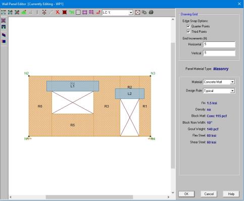
If the wall panel is drawn clockwise it will be drawn with the panel's local x-axis going from left to right. If drawn counter-clockwise the panel's x-axis will go from right to left and is presented here as though you are looking at the back side of the panel.
Note:
Creating Openings
Within the Wall Panel Editor, you have the option of adding rectangular openings to the wall panel. To draw an opening, select the Create New Openings  button and then select two grid intersections which make up the two diagonal corners of your opening. Notice that you can view your cursor coordinates in the lower right portion of your screen. The opening dimension is also displayed based on the first click of the opening relative to the second click.
To exit this tool right-click your mouse.
Note:
- Drawing an opening in a concrete wall will create a lintel above the opening. We will not design the lintel but we will give analysis results. See the Concrete Wall - Design topic on lintels.
- Drawing an opening in a masonry wall will create a lintel above the opening. For more information on defining lintel geometry and design properties, see the Masonry Wall - Design topic on lintels.
- Drawing an opening in wood wall will create a header above the opening. For more information on defining the header properties, see the Wood Wall - Design topic on headers.
- Drawing an opening in a general wall panel, there is no header/lintel automatically created. The general wall panel is given as an option for analysis only.
- Openings must be drawn greater than 3 inches away from wall edges.
Creating Regions
Within the Wall Panel Editor, you also have the option of creating different rectangular regions within your wall panel. Regions are used to further define areas of your wall panel for use in analysis/design. If you do not specify a region in a wall panel without openings, then the entire wall panel will be considered a region.
To automatically draw regions you must first have your openings input. Once you have that you can click the Generate Wall Regions Automatically button and the program will define regions as we would expect a user to want them.
Note:
- If the regions defined are not located correctly by the generator, you can delete the generated regions with the Delete
 button and redraw them manually. See below for more information on this.
To manually draw a region, select the Create New Regions  button and use your cursor to select two grid intersections which make up the diagonal corners of the region. Similar to wall openings, local coordinates and region dimensions will be displayed in the lower left corner in the Wall Panel Editor. To exit this tool right-click your mouse.
Note:
- For masonry wall panels, there is a region editor that allows you to define design properties for the region. Double-click inside the boundary of the drawn region to open this editor. See the Masonry Wall - Design topic for region information. Note that design and analysis results are displayed by region.
- For wood wall panels the design and analysis results are displayed by region.
- For concrete wall design, the program will automatically create regions at solution around openings. If there are floors/diaphragms that cut through your wall, then separate regions/designs will be created above and below the floors/diaphragms.
- For general wall panels we will not do any design for you. However, you can lay out your regions so that your analysis results will allow you to design your general wall panels much more easily.
Boundary Conditions
Within the Wall Panel Editor, all boundary conditions are applied as continuous along a wall panel edge. To set boundary conditions within the wall panel editor, select the Create New Boundary Conditions  button, select your boundary condition criteria, and select Apply. To exit out of this tool right-click your mouse. You can also apply boundary conditions to your wall panel outside of the Wall Panel Editor as well, but this is the only place where you can define a continuous boundary condition.
For wood wall panels, hold downs and straps are used in the program as well. For more information on adding hold-downs and straps, see the Wood Wall - Design topic.
Drawing Grid
The drawing grid, which appears in the upper right corner of the Wall Panel Editor screen, gives the user options for drawing within the Wall Panel Editor window. The options include:
Snap Options allows you to provide snap points at the edges of the wall panel at quarter and third points.
Grid Increments allow you to set a drawing grid within the Wall Panel Editor separate from that in the main model view that you can snap to when drawing openings and regions. This field can work in two separate ways:
- A single increment: If you put a single value here (0.5 ft for example), then this increment will be used across the entire wall until the end of the wall is reached.
- Multiple input increments: If you have specific locations you wish to define you can use this field to place exact grid points. Commas are used to delineate different grids and @ symbols can be used to apply the same increment multiple times (5, 10, 2@8, 3 for example). If you place multiple increments in and you are not yet to the end of the wall then the last increment defined will be used until the end of the wall is reached.
View Controls
In addition to the wall panel editing tools, the Wall Panel Editor window includes the following view controls:
Delete allows you to delete openings, regions or boundary conditions from the wall panel.
 Render will turn rendering of the current model view on or off, depending on the current setting.
 Nodes will show any nodes that fall in the plane of the wall panel and allow you to snap to them when drawing regions or openings.
 Drawing Grid will turn the display of the Drawing Grid on or off, depending on the current setting.
 Detach Wall Panel From Diaphragm will allow you to click on a diaphragm in the editor to detach it from the wall. The detached diaphragm will then show up in gray.
 Loads will turn the display of the wall panel loads on or off, depending on the current setting.
 Redraw Full Wall View redraws the wall panel to fit within the Wall Panel Editor window.
 Copy Current View makes a copy of the current view and saves it to the clipboard.
 Print Current View prints your current wall panel view.
Note:


- There are also view controls specific to wood. For more information see the Wood Wall - Design topic.


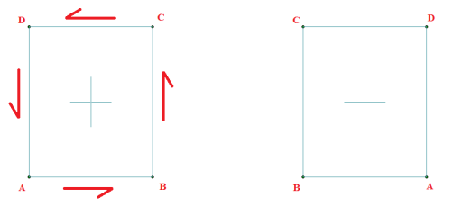
Wall Panel Local Axes
When a wall panel is drawn it comes along with a set of local axes. If the wall is drawn clockwise versus counterclockwise it will change the direction of the local axes.
In most cases the local axes direction does not affect results. Here is a list where the local axis is important:
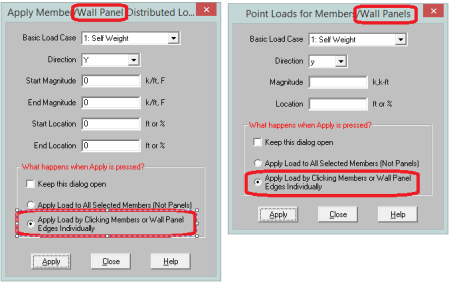
- Applying Loads: Wall panel surface loads can be applied to the local axes directions. Thus, the local axes direction will affect the sign of the applied load.
- Viewing Plate Contours: Wall plate contours can be viewed based on local axes, thus knowing the orientation is necessary to get meaningful information from these contours
- Out-of-Plane Concrete Wall Design: Concrete cover can be different for each face of a concrete wall. Which face you are defining is based on the +z and -z local axes.
Loading
Wall panels can be loaded either directly or indirectly from supporting other elements (other walls, columns, beams, etc.). Line loads and distributed loads can be applied directly to wall panels, similar to how they are applied to members. These loads can be applied vertically or horizontally. Wall panel surface loads can also be applied directly to the wall.
Load Attribution
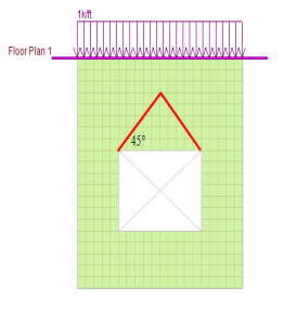
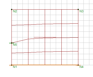
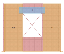
In RISA-2D, the use of finite elements dictates how loads pass through wall panels. Load is attributed to the structure according to relative stiffnesses of elements. In concrete, wood and masonry design, many empirical equations are formed based on approximations or idealizations. Because of this, you may not get your loading in your wall panel elements (regions and lintels) to match hand calculations exactly. A prime example of this occurs with the 45 degree rule for lintels for masonry. According to theory, arching action occurs in lintels to the point that, if the top of your wall is a sufficient distance away, only the load in the triangular portion above your lintel would actually be taken into the lintel itself. Also, no load applied at the floor level would be felt by the lintel either. See the image below.
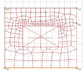
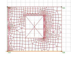
Within RISA-2D, this idealization will not hold true. The wall panel is a finite element mesh that attributes load according to the plate mesh FEM behavior. The load that is getting into the lintel is a true representation of how the wall is actually working. There is still arch action taking place as you can tell if you look at the vertical force contours in the wall panel.
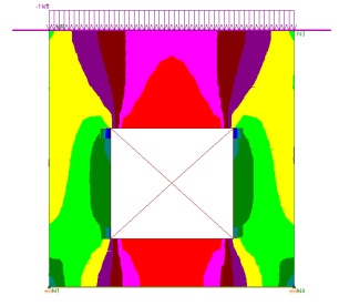
In the image above, the red color is an area of very low axial force in the wall. Thus, you can see that, due to plate distribution of force, there is still arching action taking place. This arching action, however, will not be immune to additional loads added to the wall or the opening being located lower in the wall (as is assumed with the idealized arching action in many texts). Thus, though your loads for lintel design may not be identical to what idealized methods might consider, this is a rational loading for the geometry and loading input on the wall panel.
Meshing the Wall Panels
At solution time, the wall panels will be automatically meshed into quadrilateral plate elements. Unlike the plate elements created directly by the user, the automatically generated plate elements are transient in the program and will not be saved in the input file.
The wall panel meshing is treated similar to analysis results. When the results of an analysis are deleted, the wall panel mesh is cleared to be re-built during the next solution. When a solution results file is saved, the meshed elements will be included in that file.
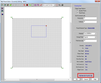
Mesh Size
The global mesh size for the wall panels can be input on the Solution tab of the Model Settings. The smaller the mesh size, the more accurate the analysis will be. However, smaller mesh size will also lead to longer solution time and more memory usage. The default mesh size is 12 inches RISA-2D.
Localized small mesh sizes are used in the lintel locations for masonry walls, in order to achieve more accuracy for the lintel forces.
Graphical Display of the Wall Panel Mesh
By default, the plate elements associated with the wall panels are not visible to the user. The mesh can be turned on using the setting on the Panels tab of the Model Display Options. The Show Mesh check box will turn the display of the wall panel mesh on or off.
- The display of the mesh is only available when there are active analysis results.
Point Constraints for the Panel Mesh
Point constraints are the locations within the wall panel that require connectivity to the meshed plate elements. The program will automatically generate point constraints at the following locations:
1. Location of an existing joint on the wall panel edges, region boundaries and opening boundaries.
2. Where beams intersects the wall panels (out-of-plane) on the wall panel edges, region boundaries and opening edges.
2. Location of an external boundary condition.
- Unattached joints that are located on the wall panels can be considered as point constraints and prolong the meshing time. It is highly recommended that the user delete any unattached joints before solving.
Line Constraints for the Panel Mesh
Line constraints are the locations within the wall panel that require continuous connectivity to plate edges rather than a single point. The program will automatically generate line constraints at the following locations:
1. Opening edges.
2. The edge and vertical centerline of a defined region.
3. Where a diaphragm intersects the wall panel.
4. Where a beam or column element intersects within the plane of the wall panel.
Tips for Ensuring an Accurate Mesh
In order to generate an efficient mesh that gives accurate results, it is critical to place the line constraints and point constraints correctly. If line constraints or point constraints are very close to each other, the auto mesher will be forced to generate small sized elements in order to satisfy the constraints. Therefore, a large number of plate elements will be generated and the solution will be slowed down significantly.
The following guidelines should be followed to ensure a quality mesh:
- Avoid generating very narrow regions and openings.
- Avoid small offsets between the external boundary conditions with the location of the region boundaries and wall boundaries.
- Avoid small offsets between opening edges with the region boundaries .
- When a wall panel is intersected by another wall panel, diaphragms, beams or plate elements, keep in mind that the intersection is a line/point constraint. Avoid the small offsets between intersections with the region boundaries or opening edges inside the wall panel.
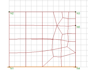
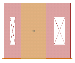
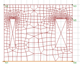
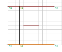
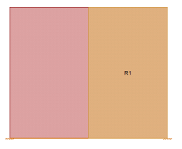
Example #1: Region Boundaries
- The left boundary region R1 is placed very close to the opening but not on the opening.
- The left boundary of region R2 is placed very closed to the left edge of the wall but not exactly on the wall boundary.
In order to satisfy the line constraints required by the opening edge, region boundaries, and wall boundaries, the program is forced to generate very small meshes in the portion of the wall adjacent to these constraints.
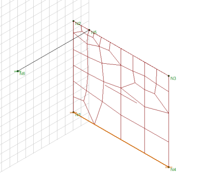
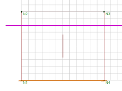
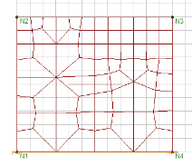
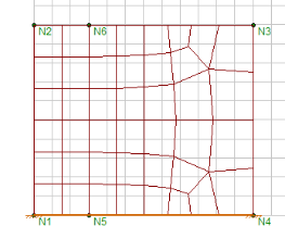
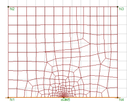
Example #2: Poorly Located Boundary Conditions:
The left boundary of region R1 is at the vertical center line of a wall panel. At the same time, the user placed an external boundary condition at the bottom of the wall panel, which is slightly offset from the center line. In order to accommodate the line constraint of the region boundary and the point constraint of the external boundary condition, the automesher is forced to generate a very small mesh adjacent to these constraints.
Merge Tolerance for Auto-Correction of Mesh
If the distance between the line constraints and point constraints are smaller than the merge tolerance specified on the Model Settings (which defaults to 0.12 inches) then the auto-mesher will automatically snap the constraints together during the meshing. This can eliminate some of the meshing issues that occur in the examples above.